


I did it!!!
Now it can easily simulate 1000 particles (on the ESP32, thanks to floating point math) and it knows about gravity  via the MPU-6050 gyro/accelerometer

I did it!!!
Now it can easily simulate 1000 particles (on the ESP32, thanks to floating point math) and it knows about gravity via the MPU-6050 gyro/accelerometer
Cyber Walkman Does It In Style https://hackaday.com/2025/01/21/cyber-walkman-does-it-in-style/ #Microcontrollers #MusicalHacks #cyberpunk #UNIHIKER #ssd1306 #Walkman #oled
Cyber Walkman Does It In Style - One of the best things about adulthood is that finally we get to, in most cases, a... - https://hackaday.com/2025/01/21/cyber-walkman-does-it-in-style/ #microcontrollers #musicalhacks #cyberpunk #unihiker #ssd1306 #walkman #oled
Редактор изображений для Arduino
В этой статье я расскажу, как из проекта по созданию метеостанции на Arduino родился проект графического редактора для подготовки bitmap-картинок. Если в ваших Arduino-проектах используется монохромный OLED-дисплей (например, SSD1306), эта статья поможет вам упростить процесс подготовки картинок для него.
My previous toot about using a #ssd1306 with all my boards reminded me that I only blogged before to explain how to connect the displays with an I2C interface but didn't the same for SPI.
So I just wrote a post doing that: https://blog.dowhile0.org/2024/09/27/using-an-spi-ssd1306-oled-on-fedora-with-a-raspberry-pi/
I have now attached a #ssd1306 display to all the embedded boards I currently have over my desk.

FML the #SSD1306 crate is not ready for async and the #oledasync does only support 1309.
Экран для вывода данных через COM-порт
Если у компьютера нет не только монитора, но и даже видео-выхода, а показания датчиков хотелось бы видеть, то решением может быть отправлять данные в виде строки в COM-порт, который будет слушать микроконтроллер и отображать приходящую строку на своём дисплее. Под катом простейшая реализация этого на микроконтроллере ATtiny13 и 0,96'-экране SSD1306 с разрешением 128х32.

@in_sympathy Linux has a graphic driver for the #SSD1306 so could just use a Python binding for any UI toolkit. You could even run a Xorg server or Wayand compositor.
Hey #fediverse , does anyone have a beginner friendly guide on creating a simple menu interface in #Python using an #ssd1306 oled screen with a #RaspberryPi ? Need to make this thing smarter 

This is a bit of an odd one, but I was asked to put something musically related together as a game to get in the spirit of the season, so I thought something along the lines of an Arduino adjustable tone generator with the aim being the player has to tune it by ear to as close to concert A – 440Hz – as possible.
This shows how I used my Nano Audio Experimenter Sheild PCB to do it. Note, as with most of my builds, this isn’t particularly mechanically satisfying, but it did the job 
Warning! I strongly recommend using old or second hand equipment for your experiments. I am not responsible for any damage to expensive instruments!
These are the key Arduino tutorials for the main concepts used in this project:
If you are new to Arduino, see the Getting Started pages.
Parts list
The Circuit
This uses the Nano Audio Experimenter Sheild PCB with the following configuration:
The photo shows the key configuration options. To get an audio output whilst using PWM, the analog GND portion of the board needs connecting to the main GND. This can be done by adding a link between the two holes highlighted below:
In my case, as I’m using a pre-build PCB I’ve added a separate single-pin header socket which then can be used to jumper across these two connectors without removing the future ability to use a DAC again.
The frequency is set using all three pots. This gives a lot more variability as a game than using a single pot. The OLED display is used to show the frequency once it has been chosen. This happens while the switch is pushed.
The Arduino tone function will be used, which provides a 0-5V DC biased square wave output. Sending this through the audio filter and output stage means that the voltage is reduced (via the resistor potential divider) and the DC bias is removed (via the coupling capacitor) so it can be used as a more typical audio line output and connected to an old amp or similar.
There are a number of options where a GPIO pin is available via a header which can then be used to connect to a simple push switch:
The downside of all of these is that my ready-made board requires header pin sockets which isn’t particularly robust for a game.
Advanced Option
But then I realised there is one additional pin exposed in a way that could still be used as an input but with a far more robust connector. D1 (TX) is linked to the MIDI OUT 5-pin DIN socket too, albeit via a 220Ω resistor. This means that I also have the option of connecting a switch across a 5-pin DIN Socket’s pins 2 (GND) and 5 (TX) and using that instead. The 5 pin DIN socket makes a much stronger and robust connection to the board, even if it is a little unconventional.
WARNING: The switch must NOT be connected between pins 4 and 5, which are the normal MIDI connections or from pin 4 to GND. Depending on the configuration used, there is a risk of connecting 5V to GND in the Arduino Nano and shorting something out. You might get away with it, depending on which resistors you end up having in the circuit (5V / 220Ω is just under 30mA), but it is really important to double checking the wiring before use!
Here is a “from the front/plug side” and “from the back/wiring side” view of a 5-pin DIN plug showing which pins are 5 and 2.
Using D1 this way means that the serial port cannot be used (even though this project isn’t using MIDI) as TX is now being reconfigured as an INPUT.
RX isn’t an option as a populated MIDI circuit has an optoisolator between the external DIN socket and the GPIO pin.
Of course if a new PCB is being used, the MIDI section can be left unpopulated and it would then be possible to directly connect one of the MIDI sockets to either RX or TX. But for this project I’m just planning on reusing my generic, fully populated board, hence RX is not an option.
The Code
The basic tone generation is simply the Arduino tone function (more here). The frequency is a simple sum of the three potentiometers giving a range from 0 up to 3069. In musical terms this spans the range of notes from A0 (and lower) almost up to G7 (just over 3kHz).
Once the choice of frequency has been made, by ear alone, the button can be pressed and the display used to show both the frequency chosen and the numerical difference from 440Hz. The winner is the person closest to 440Hz.
To add an additional feeling of skill, but in reality to add a dose of luck, I’ve added two decimal points in the display which are actually randomly chosen each time the button is pressed. The idea being that if two players both get a pretty close 440Hz then the winner is essentially selected by random!
In order to avoid having to do decimal arithmetic in the code however, when calculating the difference I’m multiplying the frequency by 100, adding in the (random) decimal as if it was just a number between 0 and 99 and then comparing the result to 44000.
D3 is selected as the audio output and D4 is selected as the trigger button for the display using the following two lines:
int SPEAKER = 3;
int TRIGGER = 4;
Additional notes from the code:
Closing Thoughts
This was a bit of a diversion and I could have easily knocked something up from solderless breadboard or stripboard with some pots and a display. But being able to just grab the PCB and experiment with the code made putting it together pretty easy.
Kevin
https://diyelectromusic.wordpress.com/2023/12/01/arduino-guess-the-frequency-game/


3-wire SPI seems almost like a taboo subject on the interwebs. Maybe it's time to change that. It exists for a reason and I intend to test its limits.
OLED Display Lets Vintage PC Engage Turbo Mode in Style https://hackaday.com/2023/07/28/oled-display-lets-vintage-pc-engage-turbo-mode-in-style/ #Retrocomputing #ArduinoHacks #turbobutton #ssd1306 #oled #486
OLED Display Lets Vintage PC Engage Turbo Mode in Style - Back in the 486 days, it was common to see a “Turbo” button on the front panel of ... - https://hackaday.com/2023/07/28/oled-display-lets-vintage-pc-engage-turbo-mode-in-style/ #retrocomputing #arduinohacks #turbobutton #ssd1306 #oled
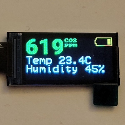
He ido haciendo mejoras y al final me ha quedado una estación meteorológica de los más apañada. Con un DHT11 leo la temperatura interior de casa. A través de internet, mediante la API que mencionaba arriba la del exterior. Lo muestro todo en un pequeño display OLED. Mostrar los datos en un tamaño decente tiene su truco.
#raspberrypipicow +
#ssd1306 +
#I2C +
#DHT11 +
#Wifi +
#Aemet Open Data
Aquí está el resultado. Ya solo queda diseñar una carcasa e imprimirla... próximamente.


 of
of